| Version 16 (modified by landauf, 8 years ago) (diff) |
|---|
Getting Started With Blender
Checked with Blender 2.48a on 4. Mar. 2009 by Felix
In this tutorial you will learn the basics of working with the 3d-modeling program Blender within one hour. Using Blender can be very confusing, especially if you have never worked with 3d-modeling software before. But don't be discouraged, once you have learned the peculiar function of the mouse in Blender and remember the most important hotkeys, you will be able to create complex scenes and objects in no time. At the end of this tutorial you will have created a simple model of a house. One more thing before you start: if you are stuck, do not hesitate to ask for help. If no help is around, write an email, use Google or check the Blender manual online for quick reference.
The User Interface
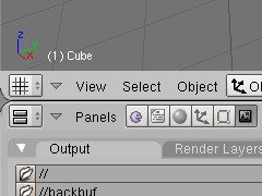
After starting Blender, you will see two large docked windows and the main menu bar at the top of the screen. The larger window is the 3D-View. Here you will see the models you create. Below there is the Buttons Window, where you can adjust properties, create different materials or render the scene. For now, some basics about using the two docked windows will be enough:
3D-View
We will now concentrate on the 3D-View, the large window showing your scene and your models. The Blender 3d-world has three cartesian coordinate axes: the x-axis (red), the y-axis (green) and the z-axis (blue). In the lower left corner of the 3D-View, you see the current orientation of the three axes. Using the number pad of your keyboard, you can adjust the view. Hit 2/4/6/8 to rotate the view in a predefined direction. Hitting 7 jumps to top view, 1 to side view and 3 is for the front view. 5 toggles between perspective view and orthonormal view. 0 on the number pad switches to camera view. Here, you will see three rectangles marking the cameras view. You will not be able to rotate in camera view, since our camera is still a static object, so you better switch back to normal with 7/1/3. With ±, you can zoom in or out. You can undo all changes to your objects by pressing Ctrl + Z.
Translation, Rotation and Scaling of Objects
Edit Mode
You now know how to transform objects in the so called Object Mode. The same transformations will also be used when we modify parts of an object. For example, we might move only one corner of an object. Select an Object and hit TAB to switch from Object mode to Edit mode. You can do this to toggle between Object and Edit mode at (almost) all times.
Extrusion Modeling
Extrusion Modeling is a simple but powerful technique to create apparently complex models. You start with a simple geometric object and extrude its faces to create more vertices. Modify the vertices and extrude more until your model has the desired shape. To benefit from extrusion technology we need three more tools. You must be in Edit mode to be able to access the right commands.
A First Model
Using Modifiers
Creating a symmetric model can save a lot of time. You do not have to model two symmetric halves, you can model one half of the model and mirror it to get the desired symmetric result. This is done using Blender's mirror modifier. There is also a modifier for making your model smoother, called Subdivision Surface Modifier (short subsurf). You'll learn how to use these modifiers, but there are many more, of course.
| Although latest space ships are not all symmetric, we will create a symmetric one here. Start with a 1x2x2 cube and subdivide it once. | 
|
| Extrude faces in x-, y-, z- and -x-direction as shown in the picture. | 
|
| Adjust the edges a little bit to form tip, cockpit and some kind of wing stubs. Of course, this is still much too blocky and doesn't look like a space ship at all yet, that's why we will use modifiers. | 
|
| To use the mirror modifier, it is best to first remove all faces in the mirroring plane. Otherwise, mirroring will result in a mesh with faces inside, a non-manifold mesh. This is something we don't want, so select the faces in the x-z-plane and erase them by hitting X and selecting Faces. | 
|
| Exit Edit mode with TAB and make sure you see the Editing menu in the buttons window (F9). Select your ship. It should by now look like the one you see on the right. You can clearly see the deleted faces on its side. | 
|
| In the Modifiers tab of the Editing menu, click Add Modifier and add the Mirror modifier. Check Y and uncheck X to mirror along the y-axis. If your model looks crappy now, make sure, the object center lies in the mirror plane. You can do this by setting the 3d-Cursor accordingly and clicking Center Cursor in the Mesh tab. | 
|
| Next, add the Subsurf modifier. Note that your model is now much smoother, because of the subdivision algorithm. You can increase the subdivision level in the mirror settings, but for now the defaults will suffice. Note: Although you added modifiers to your ship, you can still edit the basic shape in Edit mode. If you want to finally apply the modifiers, hit their Apply button. This will produce a normal mesh again without modifiers but with their changed applied to the mesh. | 
|
| Now smooth the model by clicking Set Smooth in the Link and Materials tab. If you want to learn more about smoothing, you can check out this tutorial: Smoothing with Blender. Congratulations, if both me and you didn't make any major mistakes, you successfully created something that looks roughly similar to Darkwing Duck's spaceship. Of course, there is still much work left to do, but I think you got an idea how modifiers can simplify the modelling process. | 
|
I hope you enjoyed this tutorial and did not have much trouble while following my instructions. If you want to learn more, give the other Blender Tutorials a try as well. Also check out the Blender Knowlegde Base and the Blender Hotkey Reference.
Attachments (29)
- button1.png (6.3 KB) - added by FelixSchulthess 17 years ago.
- button2.png (10.0 KB) - added by FelixSchulthess 17 years ago.
- add.png (5.8 KB) - added by FelixSchulthess 17 years ago.
- cursor.png (4.9 KB) - added by FelixSchulthess 17 years ago.
- editmode.PNG (4.3 KB) - added by FelixSchulthess 17 years ago.
- extrude.PNG (5.5 KB) - added by FelixSchulthess 17 years ago.
- grab2.png (7.8 KB) - added by FelixSchulthess 17 years ago.
- grab.png (7.3 KB) - added by FelixSchulthess 17 years ago.
- hut1.PNG (5.2 KB) - added by FelixSchulthess 17 years ago.
- hut2.PNG (5.3 KB) - added by FelixSchulthess 17 years ago.
- hut3.PNG (5.6 KB) - added by FelixSchulthess 17 years ago.
- hut4.PNG (5.9 KB) - added by FelixSchulthess 17 years ago.
- merge.PNG (5.6 KB) - added by FelixSchulthess 17 years ago.
- rotate.png (7.2 KB) - added by FelixSchulthess 17 years ago.
- scale.png (7.2 KB) - added by FelixSchulthess 17 years ago.
- select2.PNG (5.4 KB) - added by FelixSchulthess 17 years ago.
- select3.PNG (5.8 KB) - added by FelixSchulthess 17 years ago.
- select.png (7.4 KB) - added by FelixSchulthess 17 years ago.
- split.png (6.4 KB) - added by FelixSchulthess 17 years ago.
- subdivide.PNG (5.2 KB) - added by FelixSchulthess 17 years ago.
- transform.PNG (6.6 KB) - added by FelixSchulthess 16 years ago.
- ship1.png (6.2 KB) - added by FelixSchulthess 16 years ago.
- ship2.png (8.2 KB) - added by FelixSchulthess 16 years ago.
- ship3.png (8.0 KB) - added by FelixSchulthess 16 years ago.
- ship4.png (10.1 KB) - added by FelixSchulthess 16 years ago.
- ship5.png (7.4 KB) - added by FelixSchulthess 16 years ago.
- ship6.png (11.7 KB) - added by FelixSchulthess 16 years ago.
- subsurf.png (7.9 KB) - added by FelixSchulthess 16 years ago.
- mirror.png (7.8 KB) - added by FelixSchulthess 16 years ago.
Download all attachments as: .zip


